STEP 6
CALIBRATION
Calibration is the last step that should be done prior to use. For this, follow the explanations below or download PDF Step 6 – Calibration.
BEFORE STARTING
The airpointer must be calibrated at the time of installation and recalibrated as necessary.
! To ensure that high quality, accurate measurement information is obtained at all times, the airpointer must be calibrated prior to use.
! The airpointer should be in operation for at least several hours (preferably overnight) before calibration so that it isfully warmed up and its operation has stabilized.
! A calibration should only be carried out if you have sufficient time.! Please check that you have administrator rights on the airpointer.
When should you perform calibration?
- Upon initial installation
- Following physical relocation
- After any repairs or service that might affect its calibration
- Following an interruption in operation of more than a few days
- Upon any indication of analyzer malfunction or change in calibration
- At some routine interval
Here we will only discuss the calibration upon initial installation which is the calibration of the modules. Initial Calibration, Hardware Calibration and PMT Calibration have already been factory made!
Now let's start with Step 6
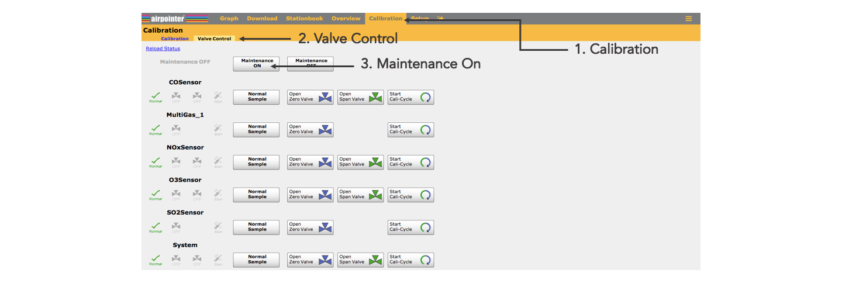
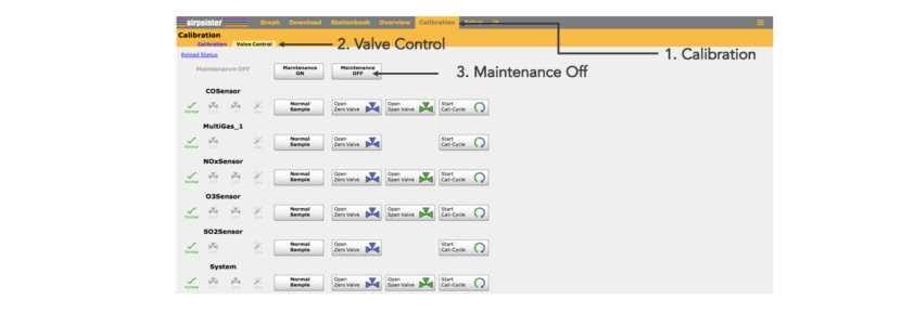
1) You should be logged in to the User Interface. Select ‘Calibration’. You will get two subsections as described below.
- Valve control
- Calibration
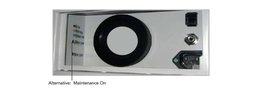
Select ‘Valve Control’ and press ‘Maintenance On’ button. You can also activate the maintenance mode by pressing the switch ‘Maintenance On’ that is in the maintenance door for 10 seconds, the respective status LEDs will change from constant to flashing light.
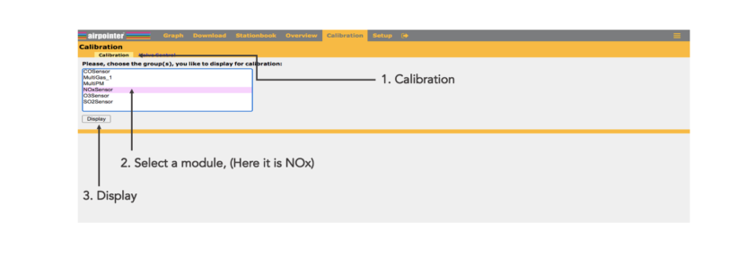
2) After switching on the maintenance mode click on ‘Calibration’ button that is next to the ‘Valve Control’. Here you can choose the gas module you want to do calibration on and than click ‘Display’. Fill in the setpoint of your span gas in ’span gas setpoint’ in given concentration. Fill in the setpoint of the external zero gas in ’zero gas setpoint’ in given concentration.
! For zero point measurement use external zero air. It can be connected in the same way as span gas.
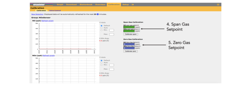
3) Apply span gas to the airpointer according to the possibilities stated (How to apply the span gas to the airpointer is explained in the next page) . Select the gas flow needed for your airpointer using the table on the right side. Apply each span gas, wait for a stable measurement signal (about 10 to 15 minutes). The measurement graph is shown on this site. When the measurement signal is stable, accept the calibration values by clicking ’calibrate span’.
Calculation: The sum of the required span gas flow is calculated by the sum of the flows for the modules installed in your airpointer plus the addition of an excess of 300ml/min. For example: Your airpointer has a O3 and SO2 module installed. The required span gas flow is therefore: 550 (O3) + 550 (SO2) + 300 (excess) = 1400ml/min. This value should be checked using your calibrated flow meter.
! In the LinSens Service Interface ‘Actual’ values are updated almost every second and therefore a more precise observation is possible there. The results of your settings can be observed immediately.
Here are the calibration gas flows:
How to apply span gas or zero air to the airpointer ?
External, using the span gas inlet at the maintenance door, Swagelok 1/4”:
The span gas tube is screwed to the Swagelok 1/4”. There is an internal T-piece for bypass for pressure compensation of the span gas. Thus, span gas flows through the T-piece to the sampling filter and further on to the sensors.
External, using the sampling hat:
In this case, the complete sampling system is included. Applying span gas is done by a hood which is put on the sampling hat. Please contact your distributor if you want to work in that way.
For applying zero air you can also use airpointer’s internal zero air supply but this is only for the use on function control.
! Dot NOT calibrate with the internal span sources ! The internal span sources are made for stability/function check only.
Applying 'Calibration Gas' to the airpointer is shown below:
4) Next, apply zero air externally to the respective sensor. Again, wait for a stable measurement (about 10 to 15 minute) and then accept the calibration value (click ’calibrate zero’). Apply each span gas, wait for a stable measurement signal (about 10 to 15 minutes) and then accept the calibration values. Repeat this procedure until the zero point deviation is within the required calibration tolerance. Calibration values are automatically stored.
Set the Maintenance Mode to ‘Off’, either by pressing the switch Maintenance Off that is in the maintenance door for 10 seconds (until the LEDs do not blink but only light) or by selecting Calibration → Valve Control → Maintenance OFF buttons in the User Interface.
! Depending on your chosen calibration philosophy the person responsible for calibration will accept the calibration factors either on-site or remotely with the opportunity to access the airpointer using the Internet. To gain stable measurement values, the system should run at least five to ten minutes.
The calibration of the airpointer is finished. Now you can start measuring! If you also would like to learn how to use 'the airpointer App', follow the next page.
DISPOSAL AND RECYCLE OF THE AIRPOINTER
After the long lasting lifetime of the unit, for the disposal please follow the local requirements of your country and dispose/recycle it accordingly.