STEP 4
FIRST START UP
The procedure in this section assumes that the airpointer is on site and all sensors are installed. You can read the explanations below or download PDF Step 4 – First Start Up.
In order to guarantee a safe and proper operation of the airpointer, several steps have to be taken before starting with the first start up. For a safe installation;
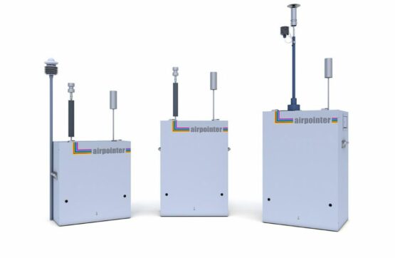
! Place the airpointer always in an upright position (now the name airpointer is readable and the sample inlet opening is on the top (see also front page)).
! Let the airpointer acclimate for at least 1 hour in an upright position before Power-Up. This will avoid damaging the cooling aggregate.Ensure sufficient space for
! Air ventilation and maintenance access above, underneath, on the right side andin front of the device by following the installation hints as it is shownin Step 3 – Mounting.
! If the airpointer contains a NOx module, its pump outlet gas releases harmful gases (NO2, and if the scrubber does not work properly, ozone). If sufficient ventilation cannot be assured, connect the pump outlet via tubing to a well-ventilated area or use a charcoal cartridge.
Now let's start with the Step 4
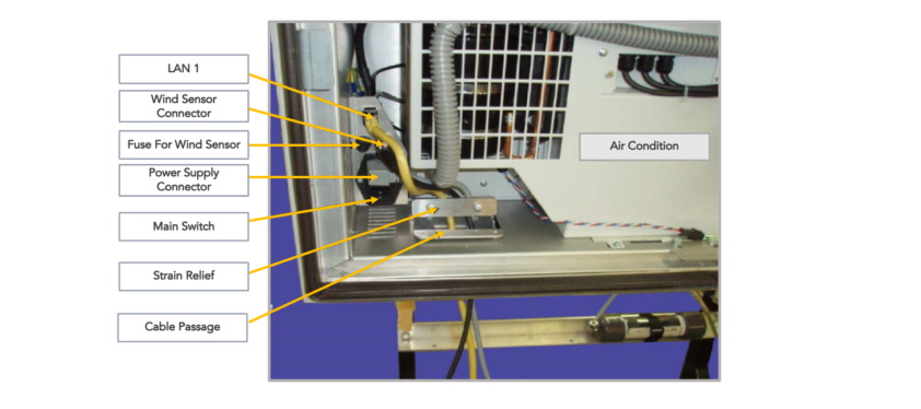
1) Open the main door. Open the cable passage and the strain relief. Lead the power line through the cable passage and connect it with the power adapter. Close the strain relief and the cable passage.
2)Check the power supply voltage. A power line 115V/60 Hz or 230V/50 Hz, min 10A fused (depending on version) is needed to operate the airpointer. Lead the power cord through the cable passage and connect it with the main power socket. The external power adapter in the maintenance access can be used to supply e.g. your notebook in the field (115VAC or 230VAC/1A maximum, depending on the version, max 100W).
3) Make sure the airpointer is connected to an appropriate grounded line.
! Do not install the airpointer in a way that emergency disruption of the power supply is obstructed.
4) To power up the airpointer, press the Master Switch. The airpointer boots up when the internal temperature is above 5°C.
! Two temperature sensors are checking the internal temperature of the airpointer. To protect the hard disk, the computer boots when the temperature is above 5°C.
5) Wait a few minutes while observing the status diodes (yellow and red LEDs light) until only the green LED lights up. The LEDs are located on the left side of the maintenance access on the right side of the airpointer housing. The pump has started by now.

6) When the green LED lights up, this means that the operating status is achieved.
7) Close main- and maintenance door.
! When closing the main door make sure that the power cord is not crimped. Use the cable passage.
At this point the airpointer will already produce data which is stored on the internal hard disk memory. Now the internet connection can be configured. For the first time this has to be done on site.
STATUS OF LEDs
At the left side of the maintenance access three Status LEDs are located. If the system is running the LEDs have a definite status.
Green: Everything is running normally, no warning.
Orange: There is at least one warning.
After the login you can see next to the name of your airpointer ‘WARN’ written in black letters. Click ‘WARN’ and a window witch detail information will be open. Alternatively, you can open the ‘LinSens Service Interface’. If you open a new window in the User Interface the sign is updated.
Red: There is at least one errors(fail).
After the login you can see next to the name of your airpointer ‘FAIL’ is written in black letters. Click ‘FAIL’ and a window witch detail information will be open. Else you can open the ‘LinSens Service Interface’. If you open a new window in the User Interface the sign is updated.
Flashing: The LEDs are flashing when the airpointer is operating in the maintenance mode. The color code is the same as described above.
All Three Light Up: The airpointer is shutting down.