STEP 5
USER INTERFACE
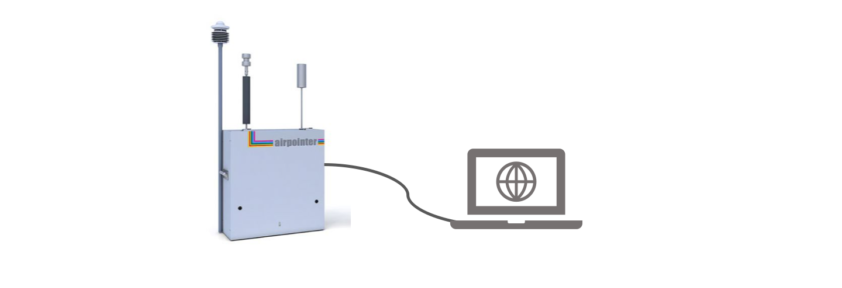
The User Interface of your airpointer is completely implemented in the software and all you need is a web browser! In terms of networking, the airpointer can be regarded as a server providing special services by its various connectors. Follow the steps below or download the PDF
Step 5 – User Interface.
BEFORE STARTING
The connection with airpointer
- Can be established directly with a cross patch cable
- Can be established as member of a local network
- Or can be established over an Internet connection
Supported web browsers are listed below:
Now let's start with Step 5
1) Make sure the airpointer is up for at least 3 minutes to have the internal computer running. Connect your Laptop with the delivered cross patch cable with the LAN connector in the maintenance door and power it up.
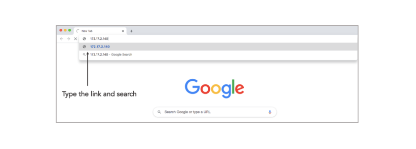
2) The Laptop will now receive an IP address from the airpointer. Open a browser and type in the address/URL bar:
172.17.2.140
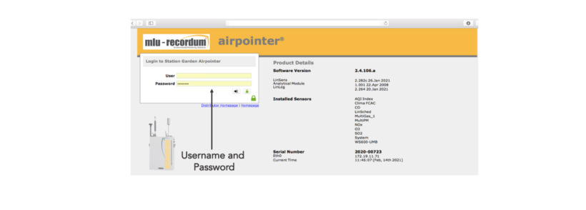
3) For login to the ‘user interface’ you have a preconfigured username and password, which is:
User: admin Password:1AQuality
IMPORTANT
! The login data are transmitted encoded to guarantee a save data handling. Now it is up to you to have your data safe.
! All airpointer users know this password and can connect to your airpointer and play around your instrument and its data. For safety reasons change the password for admin IMMEDIATELY!!!
How to change the admin password is explained in the next steps.
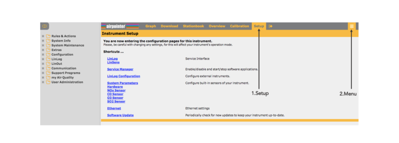
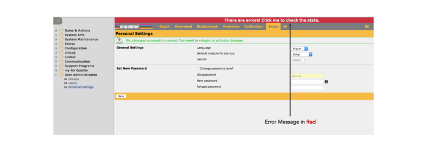
4) Change the password after the log-in. Click on ‚Setup‘ and then go to the menu sign that is on the right up corner of the page. Click on ‘User Administration’ and then ‘Personal Settings’. Change the password by typing your preferred password.
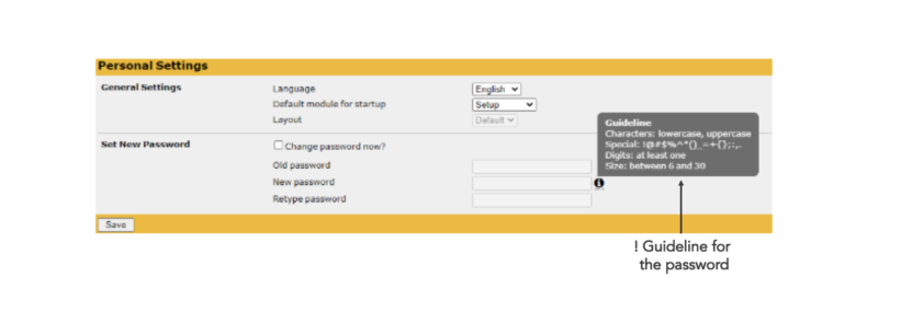
! Guidelines for the password are important. Please follow them when choosing a new password.
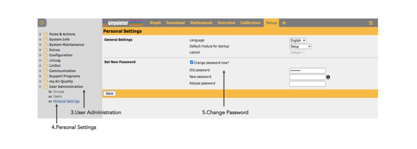
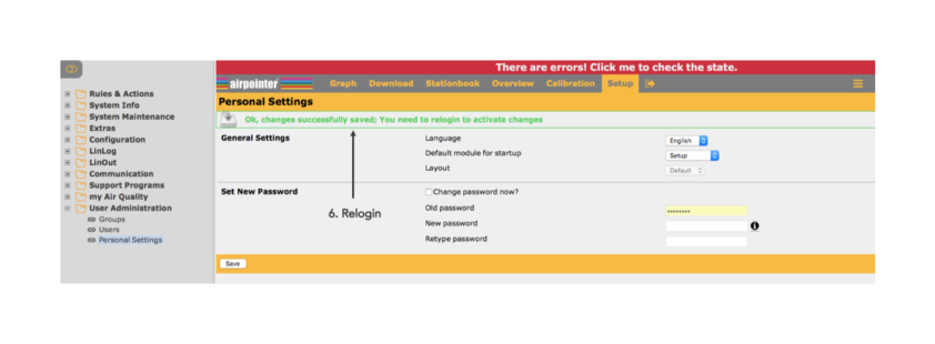
5) After changing the password , log out and relogin to activate the new password.
! Setup the modem
If you ordered the modem with your airpointer (or airQlog) most configuration steps already have been done and tested by recordum you just have to configure. Modem needs to be configured for the portal access. Please check the ink below to see how to setup the modem;
! Connecting your laptop with the airpointer via the Recordum portal:
NOTE: This is available only after the you have configured the modem and/or the system LAN setup!
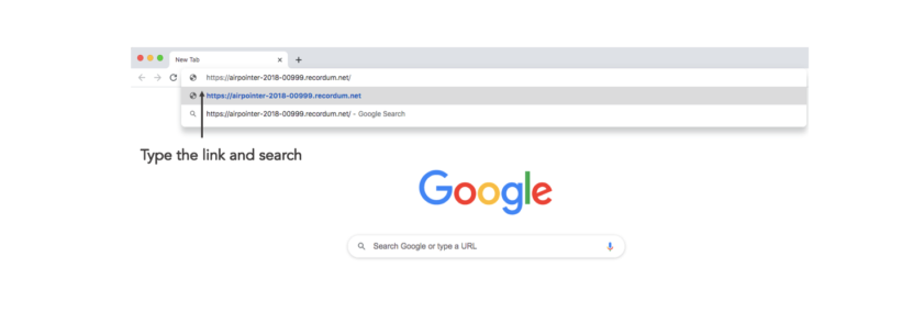
Write the link below on your web browser and search. The link for the airpointer user interface is the following;
https://airpointer-YYYY-00123.recordum.net/
The first 4 digits show the year the airpointer was produced, and the following 5 are the serial number of your airpointer. For example for an airpointer that was produced in 2018 with the serial number ‘999’, the link should look like;
https://airpointer-2018-00999.recordum.net/
! Make sure that you can log in as an administrator at your laptop and at the airpointer.
6) After the relogin to the interface, see the red error message that is on the top of the page. In the User Interface, deviations of the measurement values outside the chosen warning and failure limits are shown. Do not click on the error message at this point.
! The fail or warn sign is shown as red FAIL and orange WARN, respectively, overhead in the User Interface. (If you click the sign you will get to the LinSens Service Interface with further details (LinSens is later explained below) . Failure messages are written in red and warn messages in orange. )
FAILURE

WARNING

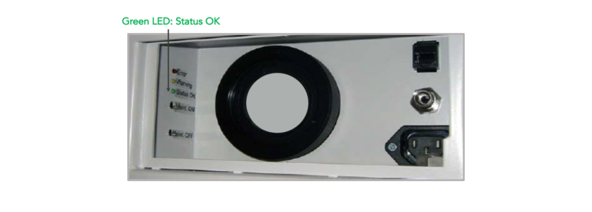
7) Wait until all warn and fail signs cease in the interface. This might require 15 to 30 minutes depending on the configuration. Then the green LED in the maintenance door lights and the airpointer is ready for operation.
8) Check the measured values on the interface, whether they are plausible (especially the temperature). All values should be within the chosen limits.
! The value -9999,0 is equivalent to a non-existing or inoperative value, analogue to MS Excel.
GET FAMILIAR – USER INTERFACE
You can read this part before or after the first operation of your airpointer and later explore the user interface. In the User Interface you will find the sections below;
Graph: It enables the presentation of measurement signals
Download: In the module Download selected measurement data can be downloaded in chosen time frame. The download
configuration can be saved locally.
Stationbook: This module provides a notepad for you.
Overview: This module is designed to give a quick summary of selected parameters. You can see your device’s
measurement data at a glance.
Calibration: The module ‘Calibration’ provides you with the items „‘Valve Control“’ and
'Calibration'. With „‘Valve Control“’ the valves of the internal zero measurement and the internal span control (optional) can be controlled. In the menu „‘Calibration“’ the setpoints for the calibration can be set and the calibration can be tracked.
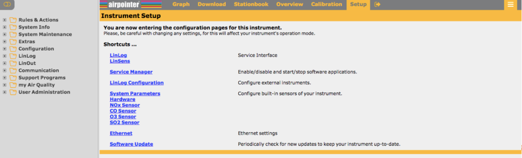
Setup: The module ‘Setup’ provides system information, configuration of sensors, system and interfaces of the airpointer. Furthermore, user management of the User Interface to the airpointer is available here.
Menu: Menu for each module can be found on the right top side of the page and it is shown with 3 lines.
Log Out: Click this tab to leave the User Interface of airpointer
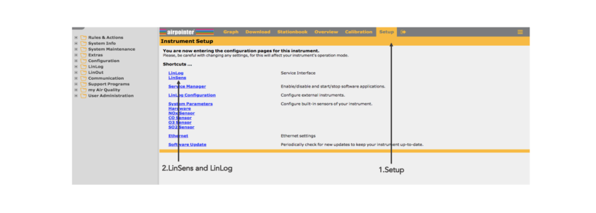
GET FAMILIAR – LINSENS AND LINLOG
Two important sub-sections on the User Interface are LinSens and LinLog. Let’s get to know these two sections before moving forward.
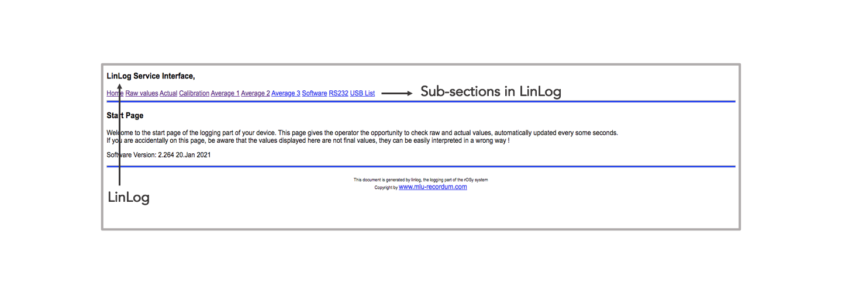
1) We reach these two sub-sections from ‘Setup’. LinLog Service Interface provides current data of airpointer’s logger. Clicking the link displays the LinLog Service Interface in a new window. (You can also reach the site, if you write your airpointer’s IP-address/linlog into your browser’s address bar) What you will find in LinLog’s sub-sections:
Home : This is the homepage with reference to the manufacturer.
Raw Values : Read in current values, arranged in groups.
Actual Values: Computed current values, arranged in groups.
Calibration: Choose group of calibration values
Average 1: Averaging of the computed
current values for average 1, arranged in groups.
Average 2
Average 3
Software: This page shows you some
software parameters like software version number.
RS232: Here you can check the communication via the COM ports.
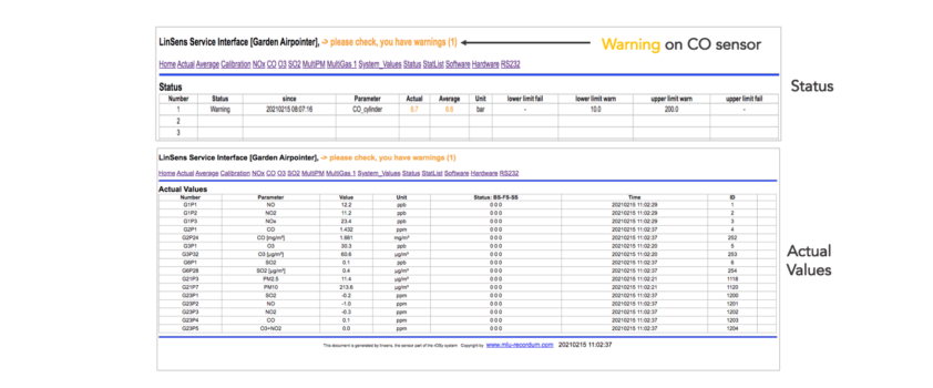
2) The LinSens Sensor Service Interface provides current sensors data of the airpointer. Clicking one of these links will open the LinSens Sensor Service Interface in a new window. The first line shows the operation mode of the airpointer. Normal operation in black letters means everything is functioning well. Normal operation in red letters additionally displays the values considered to be faulty.
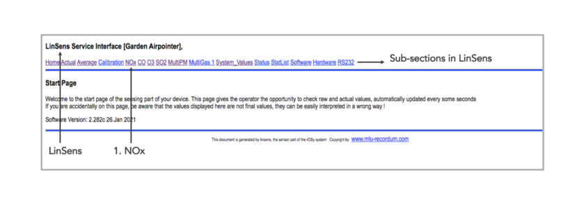
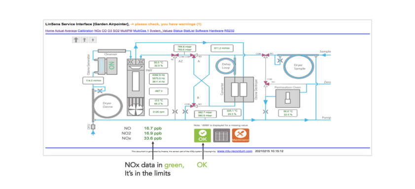
3) Let’s choose sensor NOx here (you can see all the sensors you have and also the system values in the same way). You will see the current data of the sensor module NOx. Colour codes in LinSens will inform you about the warnings, values that exceed the limit or maintenance warnings. If all the values are normal and there is no warning/error then you will see these data in green. Here are the meanings of the colours and examples:
OK

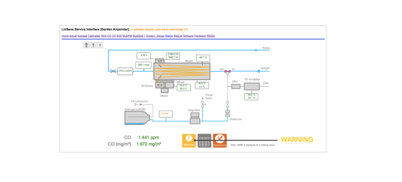
WARNING

MAINTENANCE

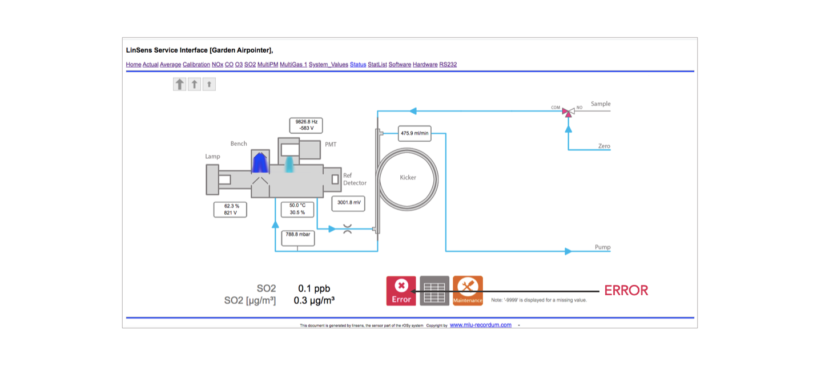
ERROR

Other examples colour code examples from CO and SO2 sensors:
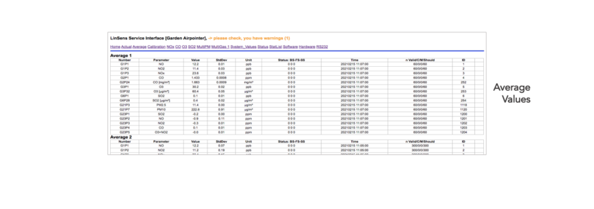
4) Some other sub-sections are in LinSens are ‘Actual System Values’, ‘Average values’ and ‘Status’. Here you will see the real time or average data on your sensors.