STEP 3
MOUNTING
Please read the instructions below carefully to understand how to mount the airpointer. You can also download the PDF Step 3.
BEFORE STARTING
IMPORTANT
! For air quality measurement, free air circulation is essential. Please refer to the requirements for selection of a good mounting site for the airpointer.
! Small corners are not recommended for the mounting area. This can cause airpointer to heat up!
! Power connection 115V/60 Hz or 230V/50 Hz, min 10A fused (depending on version) is needed at the installation site. Optionally, establishing internet connection for the airpointer preparations may be necessary.
CAUTION: Ensure the airpointer is operated in a sufficiently ventilated area. If the airpointer contains a NOx module, its pump outlet gas contains NO2 and – in case the ozone killer does not work properly– also ozone. If sufficient ventilation cannot be assured, connect the pump outlet via tubing to a well-ventilated area. If an airpointer with NOx module is used indoors use a charcoal scrubber (part number: 800-201300).
Required Ventilation Clearance and Maintenance Space:
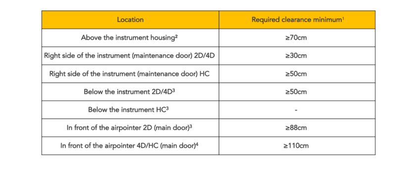
1. For air quality measurement free air-streams are essential. Please refer to local requirements for selection of a good site for the airpointer.
2. Minimum distance required for installation of the sampling head; for indoor use make sure that the clearance is large enough to allow undisturbed sampling.
3. If you have less front space, please contact your distributor for special solutions
Now Let's Start
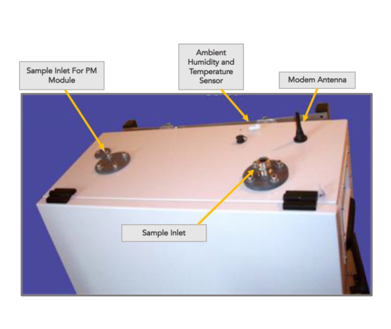
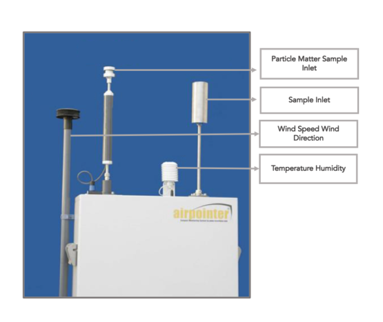
1) Loosen the screw for the sample inlet. Push the sample inlet into its final position and fasten the screw till the sample inlet cannot be rotated any more. Sample inlet location is shown on the photo on the right side. Mount all external sensors (optional) and connect them. The wind sensor is fixed with a collar on the left side, all other sensors (e.g.: humidity and temperature), the modem and the sample inlet for particle measurement are mounted and connected on the top of the airpointer.
! The Wind Sensor should be turned until it faces north.
! There are little marks on the different sensors that should face north
Loosen the screws of the sample inlet.
Mount the extrenal sensors.
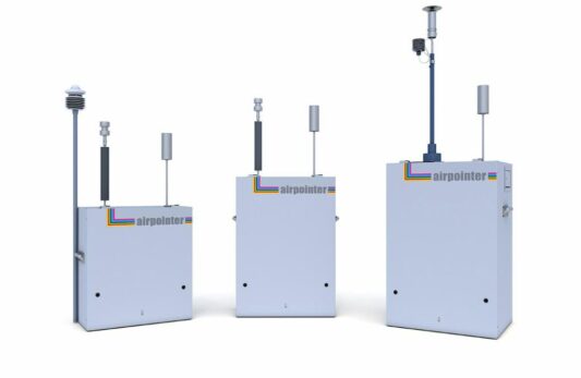
2) The airpointer should be mounted stationary. We recommend using one of three mounting kits available. Mounting Kit M for mast mounting (with variable or fixed diameter) and Mounting Kit W for wall mounting.
Wall Mounting Kit W: Place each of the four wall mounting kits vertically and fix them with 2 M10 washers and screws delivered with the kit.
Mast Mounting Kit M: Place each of the two mast mounting kits horizontally and fix them with 4 M10 washers and screws delivered with the kit.
Further Mounting possibilities: Please ask your distributor for additional mounting possibilities (e.g.: lift mounting and trolley).
! Use the four M10 screws on the back side of the housing for Wall Mounting or Mast Mounting the airpointer, only.
! The two handles on the left and on the right side of the airpointer have only to be used for lifting the airpointer. DO NOT use these handles for permanent fixation.
! Check once again that the two red coloured shipping screws from the bottom of the pump room are already removed. If not, please do so now as showed in Step 2.
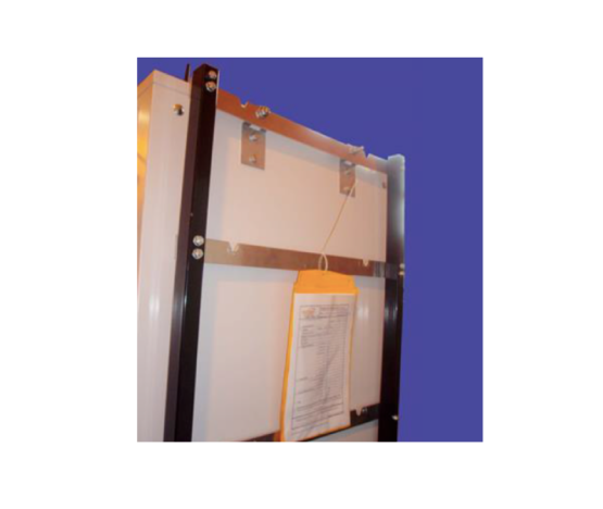
Fixation of mounting kit W for wall mounting on a frame.
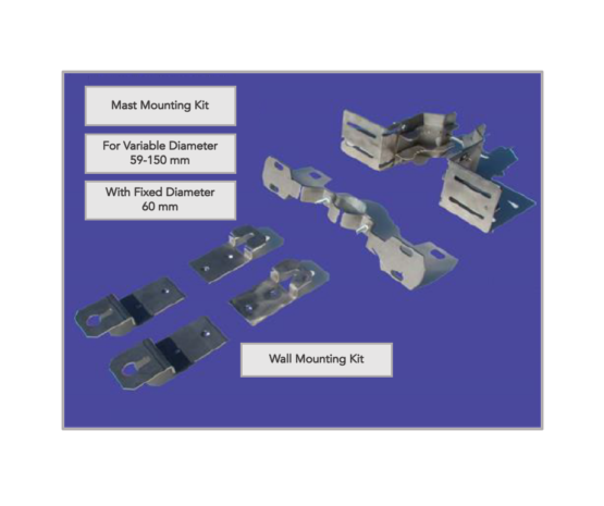
Clamping claws and mounting brackets.